NEWS

A moulded case circuit breaker (MCCB) is a type of electrical protection device that is used to protect the electrical circuit from excessive current, which can cause overload or short circuit. With a current rating of up to 1600A, MCCBs can be used for a wide range of voltages and frequencies with adjustable trip settings. These breakers are used instead of miniature circuit breakers (MCBs) in large scale PV systems for system isolation and protection purposes.

How the MCCB operates

The MCCB uses a temperature sensitiv‘e device (the thermal element) with a current sensitive electromagnetic device (the magnetic element) to provide the trip mechanism for protection and isolation purposes. This enables the MCCB to provide:
•Overload Protection,
•Electrical Fault Protection against short circuit currents
•Electrical Switch for disconnection.
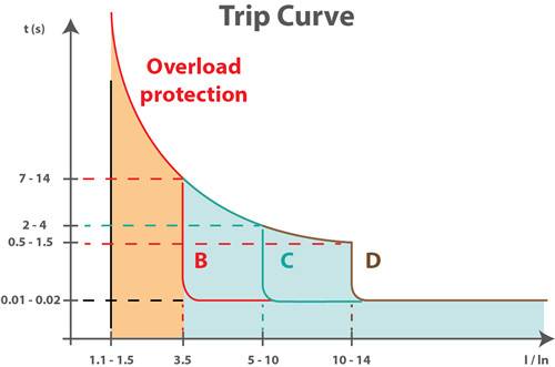
Overload Protection

Overload protection is provided by the MCCB via the temperature sensitive component. This component is essentially a bimetallic contact: a contact which consists of two metals that expand at different rates when exposed to high temperature. During the normal operating conditions, the bimetallic contact will allow the electric current to flow through the MCCB. When the current exceeds the trip value, the bimetallic contact will start to heat and bend away due to the different thermal rate of heat expansion within the contact. Eventually, the contact will bend to the point of physically pushing the trip bar and unlatching the contacts, causing the circuit to be interrupted.

The thermal protection of the MCCB will typically have a time delay to allow a short duration of overcurrent which is commonly seen in some device operations, such as inrush currents seen when starting motors. This time delay allows the circuit to continue to operate in these circumstances without tripping the MCCB.

Electrical Fault Protection against short circuit currents

MCCBs provides an instantaneous response to a short circuit fault, based on the principle of electromagnetism. The MCCB contains a solenoid coil which generates a small electromagnetic field when current passes through the MCCB. During normal operation, the electromagnetic field generated by the solenoid coil is negligible. However, when a short circuit fault occurs in the circuit, a large current begins to flow through the solenoid and, as a result, a strong electromagnetic field is established which attracts the trip bar and opens the contacts.

Electrical Switch for disconnection

In addition to tripping mechanisms, MCCBs can also be used as manual disconnection switches in case of emergency or maintenance operations. An arc can be created when the contact opens. To combat this, MCCBs have internal arc dissipation mechanisms to quench the arc.
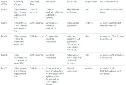
Deciphering MCCB Characteristics and Ratings

MCCB manufacturers are required to provide the operating characteristics of the MCCB. Some of the common parameters are explained below:
Rated Frame Current (Inm):
The maximum current that the MCCB is rated to handle. This rated frame current defines the upper limit of the adjustable trip current range. This value determines the breaker frame size.
Rated Current (In):
The rated current value determines when the MCCB trips due to overload protection. This value can be adjusted, to a maximum of the rated frame current.
Rated Insulation Voltage (Ui):
This value indicates the maximum voltage which the MCCB can resist in lab conditions. The rated voltage of MCCB is typically lower than this value to provide a safety margin.
Rated Working Voltage (Ue):
This value is the rated voltage for the continuous operation of MCCB. It is normally the same as or close to the system voltage.
Rated Impulse Withstand Voltage (Uimp):
This value is the transient peak voltage the circuit breaker can withstand from switching surges or lightning strikes. This value determines the ability of the MCCB to withstand transient over-voltages. The standard size for impulse testing is 1.2/50µs.
Operating Short Circuit Breaking Capacity (Ics):
This is the highest fault current that the MCCB can handle without being permanently damaged. MCCBs are generally reusable after fault interruption operation provided they do not exceed this value. The higher the Ics, the more reliable the circuit breaker.
Ultimate Short Circuit Breaking Capacity (Icu):
This is the highest fault current value that the MCCB can handle.If the fault current exceeds this value, the MCCB will be unable to trip. In this event, another protection mechanism with a higher breaking capacity must operate. This indicates the operation reliability of the MCCB.It is important to note that if the fault current exceeds Ics but does not exceed Icu, the MCCB can still remove the fault, but may be damaged and require replacement.
Mechanical Life:This is the maximum number of times the MCCB can be operated manually before it fails.
Electrical Life:This is the maximum number of times the MCCB can trip before it fails.

Sizing the MCCB

MCCBs in an electrical circuit should be sized according to the circuit’s expected operating current and possible fault currents. The three main criteria while selecting MCCBs are:
•The rated working voltage (Ue) of the MCCB should be similar to the system voltage.
•The trip value of the MCCB should be adjusted according to the current drawn by the load.
•The breaking capacity of the MCCB must be higher than the theoretical possible fault currents.

Types of MCCB

news news

Figure 1: Trip curve of type B, C, and D MCCBs

MCCB Maintenance

MCCBs are subjected to high currents; therefore maintenance of MCCBs is critical for reliable operation. Some of the maintenance procedures are discussed below:

1. Visual Inspection
During the visual inspection of a MCCB, it is important to look out for deformed contacts or cracks in casing or insulation. Any burn marks on contact or casing should be treated with caution.

2. Lubrication
Some MCCBs require adequate lubrication to ensure the smooth operation of the manual disconnection switch and internal moving parts.

3. Cleaning
The dirt deposits on MCCBs can deteriorate the MCCB components. If the dirt includes any conducting material it may create a path for current and cause an internal fault.

4. Testing
There are three main tests that are carried out as a part of maintenance procedure of a MCCB.
Insulation Resistance Test:
The tests for a MCCB should be conducted by disconnecting the MCCB and testing the insulation between the phases and across the supply and load terminals. If the measured insulation resistance is lower than the manufacturer’s recommended insulation resistance value then the MCCB will not be able to provide adequate protection.

Contact Resistance
This test is conducted by testing the resistance of the electrical contacts. The measured value is compared to the value specified by the manufacturer. Under normal operating conditions, contact resistance is very low since MCCBs must allow operating current through with minimum losses.

Tripping Test
This test is conducted by testing the response of the MCCB under simulated overcurrent and fault conditions. Thermal protection of the MCCB is tested by running a large current through the MCCB (300% of rated value). If the breaker fails to trip, it is an indication of failure of thermal protection. The test for magnetic protection is conducted by running short pulses of very high current. Under normal conditions, magnetic protection is instant. This test should be conducted at the very end as high currents increase the temperature of contacts and insulation, and this may alter the results of other two tests.

Conclusion
The correct selection of MCCBs for the required application is key to providing adequate protection in sites with high power equipment. It is also important to carry out maintenance actions at regular intervals and each time after trip mechanisms have been activated to ensure the safety of the site is maintained.


Post time: Nov-25-2020